Telluric Transmission Testing Deck Completed
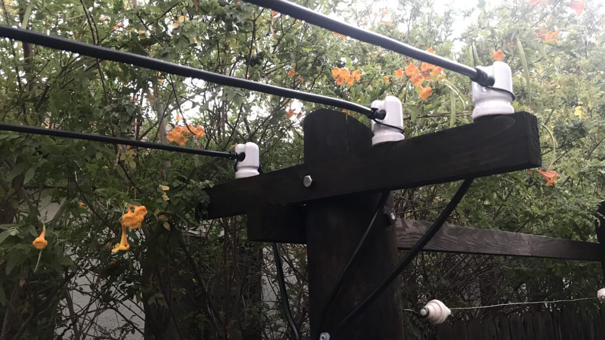
Despite the intense heat of the summer, the primordial construction of the telluric test platform has now been finalized with all necessary coax connections secured.
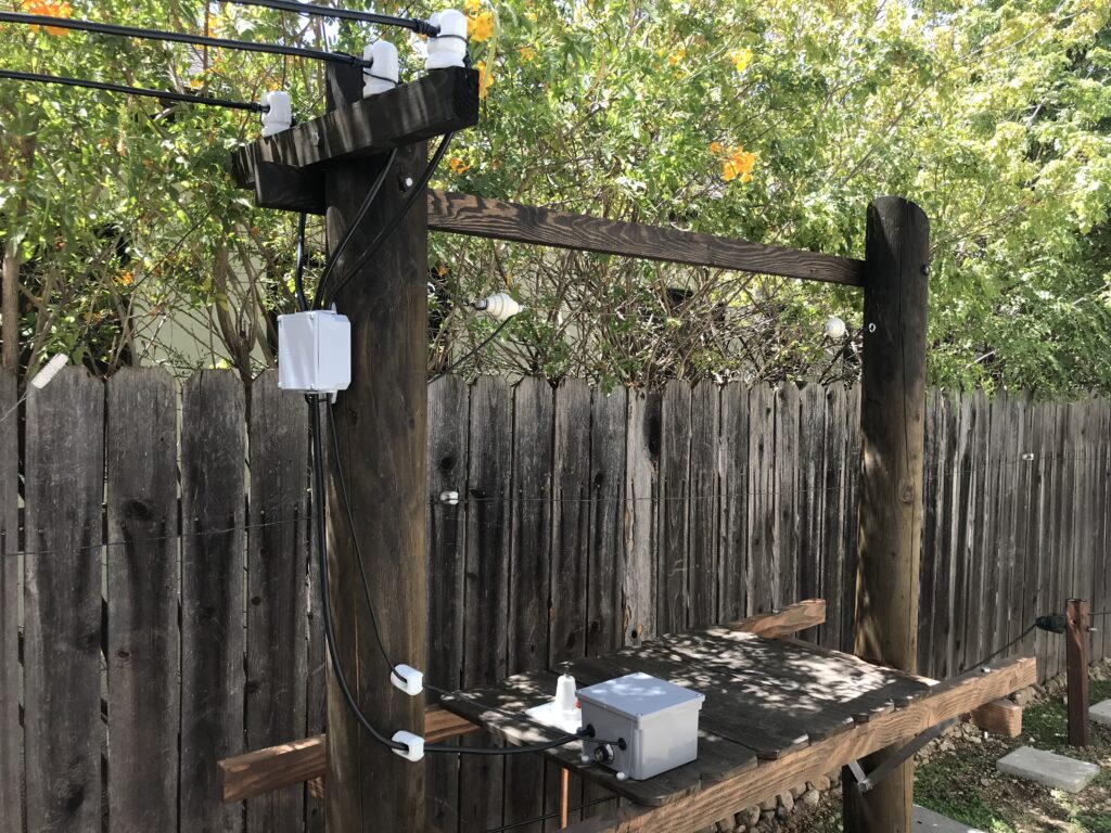
To accommodate the physical layout of the surrounding area, some slight changes to the original design as put forth by Eric Dollard had occurred. Without deviating far from the design, most changes were beneficial add-ons.
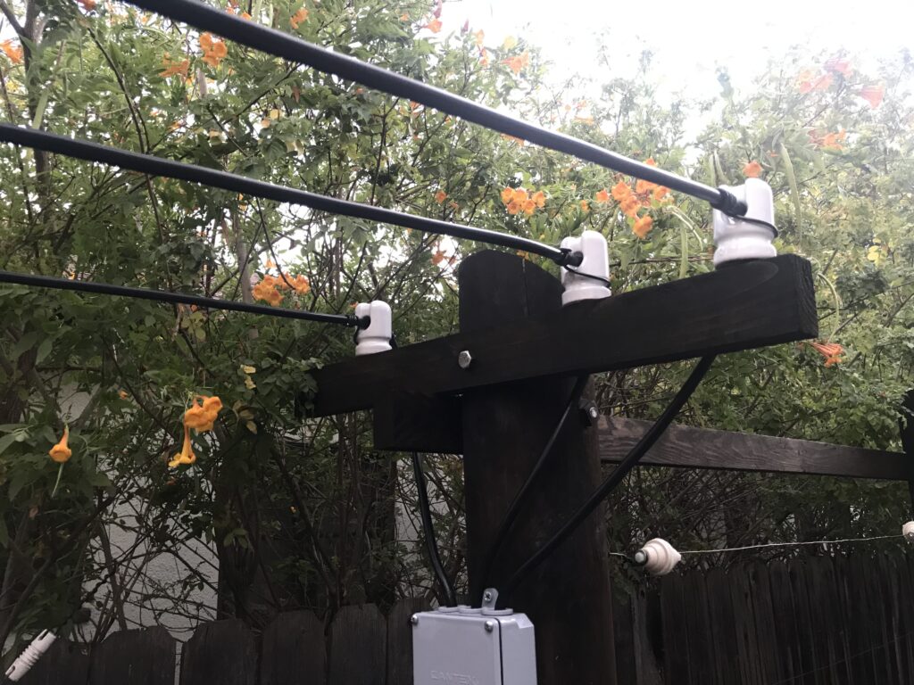
The above image showcases the three main connections to the testing deck, with the left most line connecting to the potential pick-up probe, the center being the sole RF supply line, and the rightmost being the Earth current measuring line. Both the potential and current measuring probes will help indicate the most suitable transmission and reception arrangement of the phases alongside the coil setup.
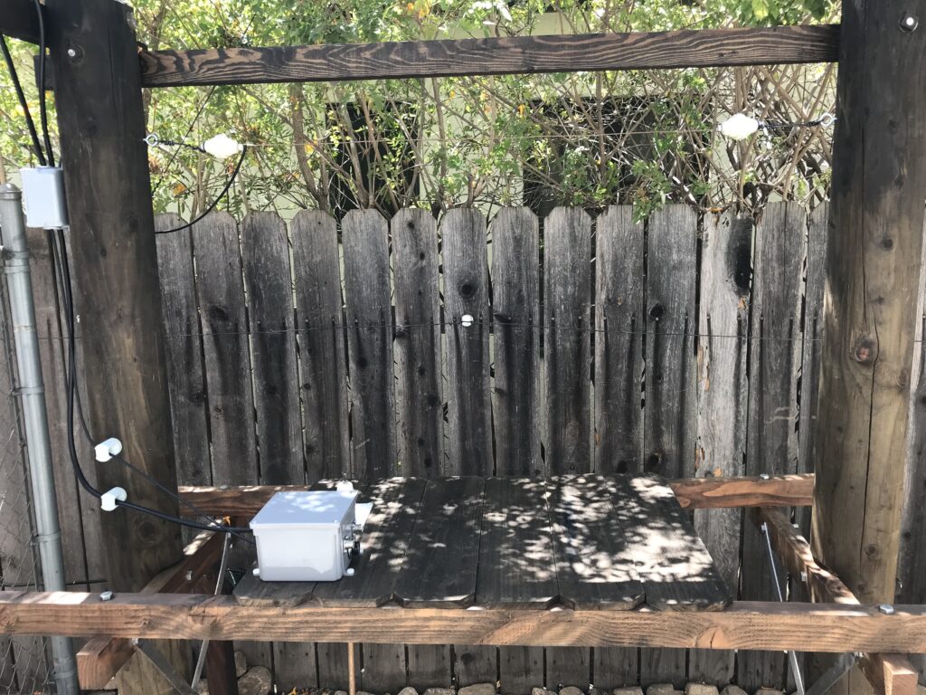
It will be noticed that the grey connection box located on the deck itself allows for RF connection to the coil in question, as well as a removable connection for adaptive Earth current measuring probes.
Keeping in mind the limited space of this suburban backyard environment, all constructions including the testing deck have to be carefully designed. That is, all feed lines and conductive surfaces should not intermingle with other electrostatic – radio frequency circuits, or do so at the very minimum. This is prevented by transposing connections, and simply securing all feed lines properly and durably.
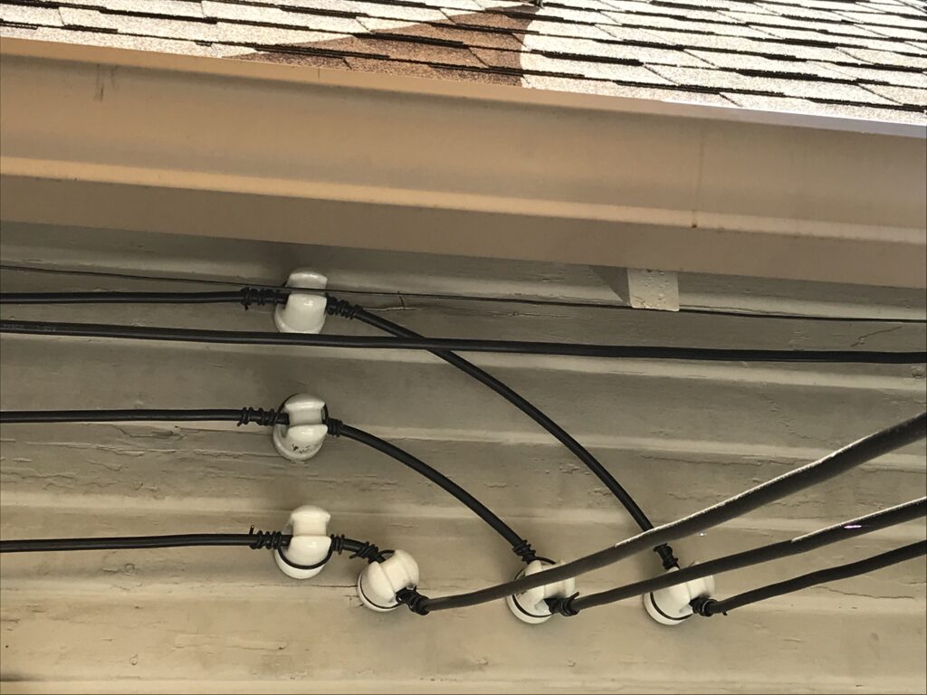
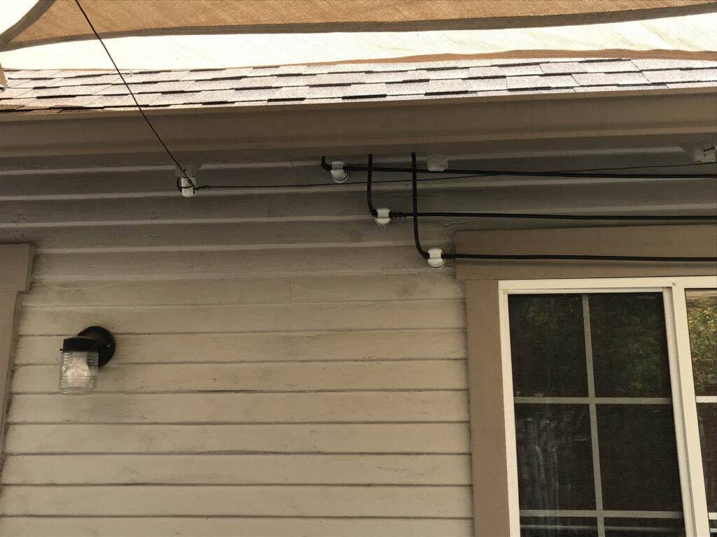
Once outdoor temperatures reduce themselves to a more work efficient degree, great lengths of experimentation will occur involving the new deck setup and ground plane.
Share this:
- Click to share on Twitter (Opens in new window)
- Click to share on Facebook (Opens in new window)
- Click to share on Pinterest (Opens in new window)
- Click to share on LinkedIn (Opens in new window)
- More
- Click to share on Reddit (Opens in new window)
- Click to share on WhatsApp (Opens in new window)
- Click to share on Mastodon (Opens in new window)
- Click to share on Telegram (Opens in new window)
- Click to share on Tumblr (Opens in new window)
- Click to share on Nextdoor (Opens in new window)
- Click to share on Pocket (Opens in new window)
- Click to email a link to a friend (Opens in new window)
