Seismic Forecasting Station Ionospheric Flat Top Antenna

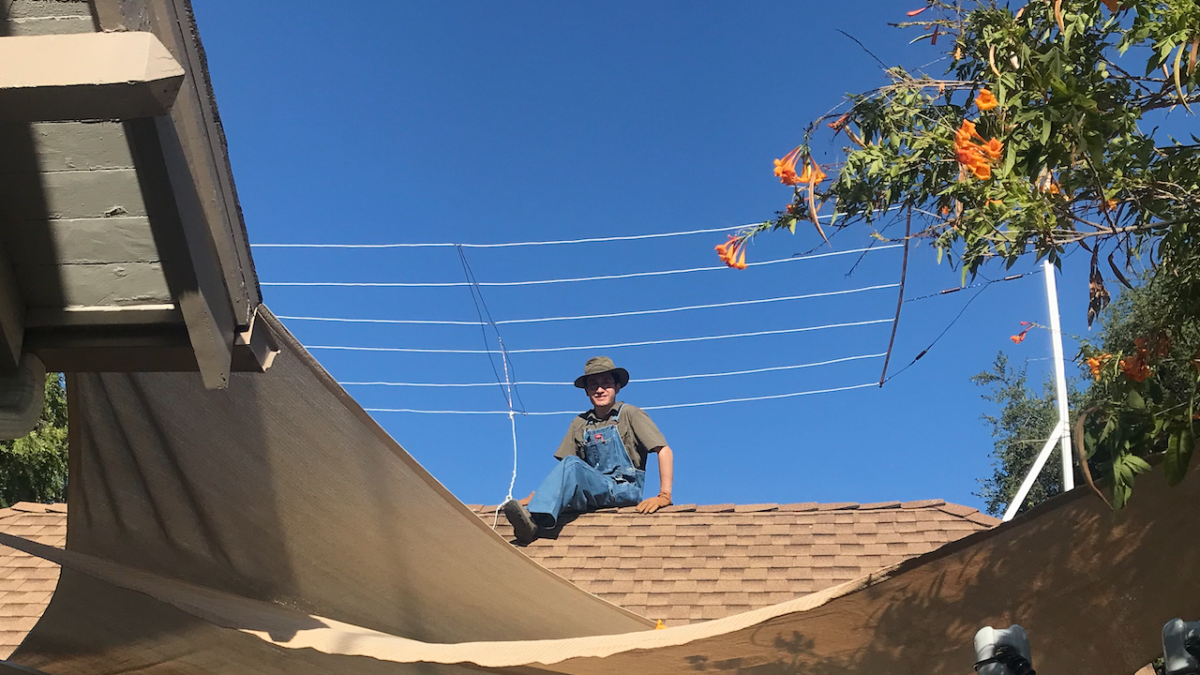
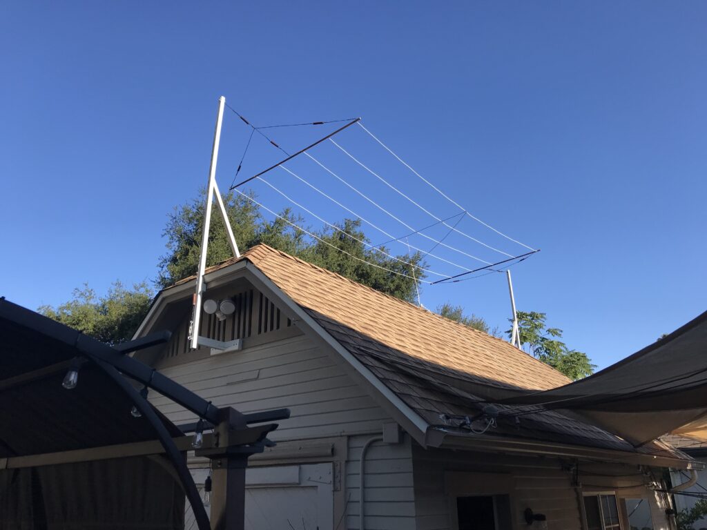
As current attention has shifted aside from conference related material, the finalizing touches to the current suburban based seismic forecasting station has been underway. In terms of receiving the ionospheric-electrostatic component of such seismic events, a Marconi style flat top antenna has been erected as shown below.

As opposed to the classical construction design of an early flat top antenna, this derivative of such does not possesses a definite wavelength with intention. Likewise, the interference of radio frequency sources which would otherwise resonate more readily if the antenna were constructed with insulative lines, would intern produce vast signal overloading. That is, the intended VLF seismic signals would likely be abstained from reception, as the locality of nearby broadcast transmitters and their ground wave signal strength would be of immense proportion. To understand the difference of this antenna as opposed to a typical flat antenna, the below figure should be adhered to.

The core function of a traditional flat top antenna is to act as a vertical radiating element, shown by the vertical feed wire in both (a) and (b). The objective in both conditions is to impose a capacitive body atop this vertical radiator, as to lower the operating frequency of the vertical element, without having to increase its height/length in proportion to its desired operating frequency. While this capacity accomplishes this, the current distribution of the radiating element is proportional to a perpendicular relationship with that of the vertically polarized dielectric field being emitted off of it. That is, the radiating element still behaves as any ordinary vertical radiator. The capacitive body, shown as parallel conducting wires suspended above the vertical element and secured as proper, enable a further current distribution along this capacitance body, thus creating a situation whereby a coupling is established with the ionosphere in terms of lines of force. It should be noted that for optimal operation of a flat top antenna in use for the broadcasting of low frequency, a highly adequate ground system must be secured. Without such a construct, the large capacitance of the top most section (the flat top) will impose an electrical imbalance of the radiated wave. Hence, the transmitted wave would not maintain a mutual Earth to Ionosphere strength, giving the strength of the wave poorly irrespective to that of the Earth and its conductive influence. Likewise, the use of flat top antennas in early maritime communications were employed aboard ships, whereby the hull of the vessel provided a low impedance Earth connection with the surrounding saltwater aiding in Earth-coupling.
For the purpose of the previously stated seismic forecasting ventures, the flat top antenna shown in the first photograph in reality is not an actual antenna. That is, its wavelength is cancelled out by having its six suspended conductors terminating on a central copper support tube, 0.5 inches in diameter. This creates a uniform capacitance of which is distributed over the antenna’s entire surface area. Specifically, this antenna has a width of 6.5 feet, by 18 feet in length. Thus, its capacitive surface area equates to 117 square feet, similar to that of a 20 foot suspended metal sheet of the same surface area. (Further analysis of the antenna’s electrical characteristics will be made in a follow-up post.) As in a general description of this antenna, ceramic strain insulators, guy lines, and soldered connections have been employed to maximize strength and efficiency of the setup.
Share this:
- Click to share on Twitter (Opens in new window)
- Click to share on Facebook (Opens in new window)
- Click to share on Pinterest (Opens in new window)
- Click to share on LinkedIn (Opens in new window)
- More
- Click to share on Reddit (Opens in new window)
- Click to share on WhatsApp (Opens in new window)
- Click to share on Mastodon (Opens in new window)
- Click to share on Telegram (Opens in new window)
- Click to share on Tumblr (Opens in new window)
- Click to share on Nextdoor (Opens in new window)
- Click to share on Pocket (Opens in new window)
- Click to email a link to a friend (Opens in new window)

