Determining The Hertzian & Telluric Frequency Modes of A Coil
In order for the proper operation of a single resonant coil or tandem set, such as a Tesla Magnifying Transmitter to correctly maintain a Telluric propagation through the natural media, the consideration of the “dual mode” effect must be examined. This effect presents itself by observing two resonant frequencies being present, with one existing near the observed quarter wavelength frequency (the parallel mode), and characteristic higher impedance frequency (the series mode), set at a higher frequency interval. This is greatly evident in single coil operation, as multiple coils would otherwise present greater difficulty in determination. For this purpose, this article will solely pertain to the single coil for simplicity, although such a setup may not be suitable for Telluric communication.
The present method for quantitatively determining the series and parallel modes of resonance is via a Vector Network Analyzer (VNA). Consideration has been brought to the author’s attention that this form of measuring may not be appropriate for monopolar coil apparati, as a VNA device is a two phase measuring system, not considering the strictly single phase characteristic nature of a resonant coil(s) intended for Telluric propagation.
Throughout the course of employing VNA measurements to determine such modes, it has been recently found that by simply inspecting the phase alignment of the potential and current nodes alongside a resonant coil, correlation may be made to approximately evaluate the series and parallel modes of operation. To this effect, the following experiment was conducted with a high efficiency – high magnification factor coil intended for the 40 meter amateur radio band.
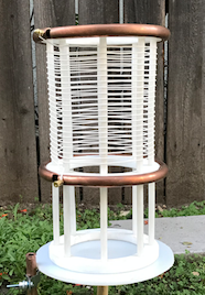
With aid of a signal generator and field strength meter, the coil shown above possesses a characteristic Hertzian frequency of 6.94 Megacycles. This frequency may be also classified as the natural parallel frequency mode. This can be conceived visually by the below VNA plot diagram.
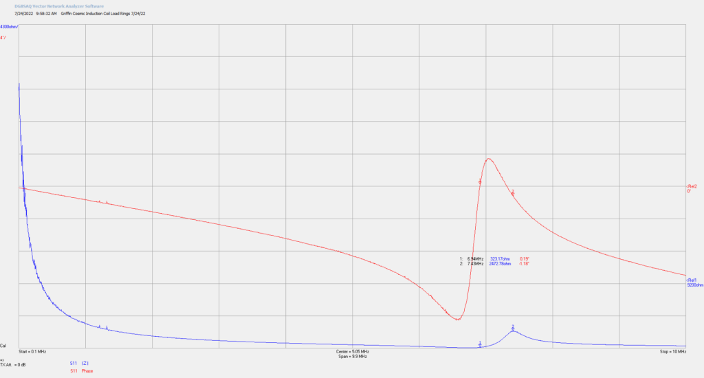
Hereby, the parallel mode of operation is found to be exactly 6.94 Megacycles, and the corresponding series mode to be 7.43 Megacycles. It may be mathematically reasoned that the proportionality of the series mode to the parallel mode is approximately 107 per cent, corresponding to a general proportionality factor of 107 per cent to 109 per cent. As will be noted in following articles to come, this proportionality holds to be true to a strict degree, with a purpose still under investigation at the present.
With these measurements in mind, figure (3) displays the test configuration employed, having the resonant coil series fed by a signal generator and Earth ground. The Earth terminal in this circumstance was an established grounded barrel, as described in previous posts.
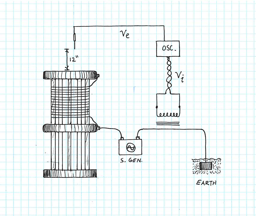
Hence, the oscilloscope represented by (Osc.) measures the electrostatic potential emanating from the top terminal of the coil, Ve, using a straight wire of four inches in length, hanging above the coil’s terminal at a distance of 12 inches. The characteristic current node of the coil, Vi, is likewise measured by an inductive ferrite core coil with an inductance of 1.6 mili-Henry, indirectly coupled to the Earthed lead. This allows for the determination of the “voltage” and “current” phase alignments of the coil with respect to a change in frequency. Along with overall induced voltage peak to peak and amplitude measurements.
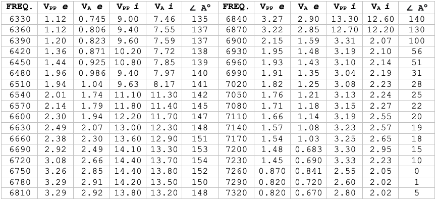
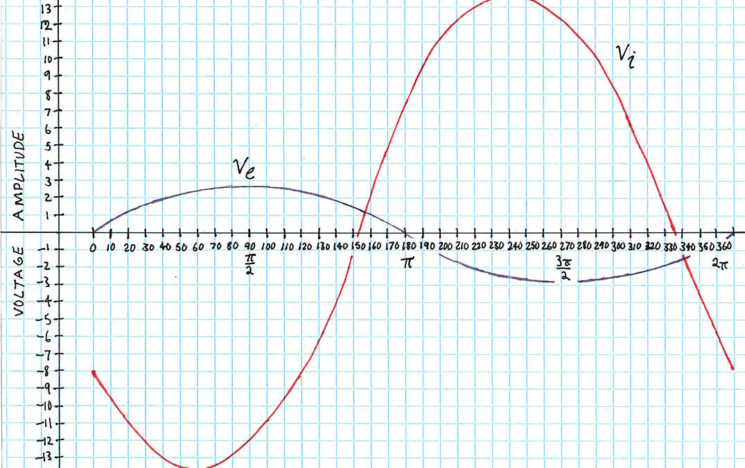
The resulting frequency changes as observed from the VNA plot, give the new parallel mode frequency as 6.72 Megacycles, and the series mode as 7.26 Megacycles. This frequency decrement is a resultant of the series connected Earth terminal burdening the frequency. Nonetheless, the same series to parallel mode ratio of 107 percent still prevails. With this, the following phase alignment graphs may be determined.
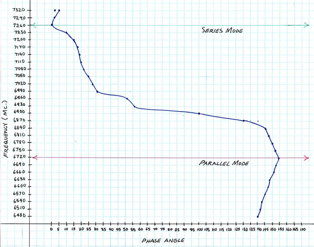
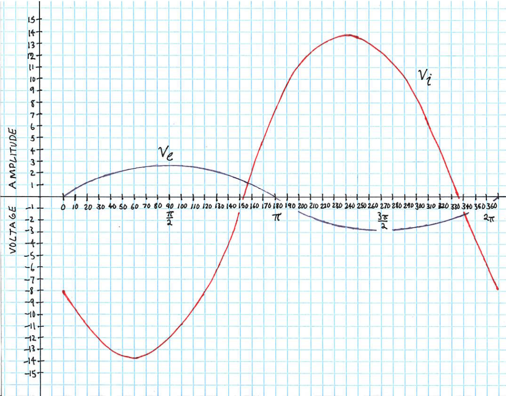
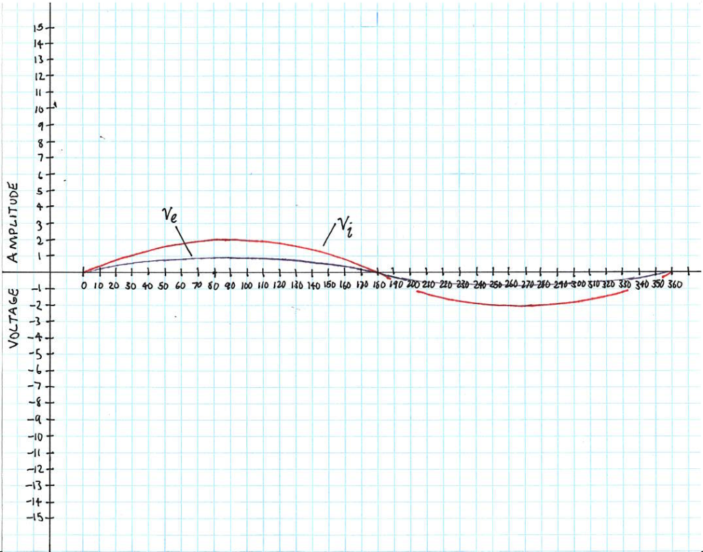
Thus, it may be roughly reasoned that the determination of the series mode intended for Telluric operation is dependent upon the phase alignments of the potential and current nodes along side a resonant coil apparatus. That is, for the series mode to prevail, the alignment of the potential node must be in direct phase alignment with that of the current node.
Share this:
- Click to share on Twitter (Opens in new window)
- Click to share on Facebook (Opens in new window)
- Click to share on Pinterest (Opens in new window)
- Click to share on LinkedIn (Opens in new window)
- More
- Click to share on Reddit (Opens in new window)
- Click to share on WhatsApp (Opens in new window)
- Click to share on Mastodon (Opens in new window)
- Click to share on Telegram (Opens in new window)
- Click to share on Tumblr (Opens in new window)
- Click to share on Nextdoor (Opens in new window)
- Click to share on Pocket (Opens in new window)
- Click to email a link to a friend (Opens in new window)
