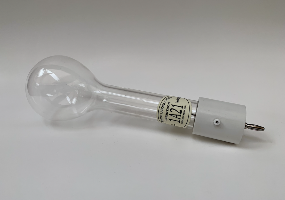
In the realm of both historical and scientific replication of Nikola Tesla’s work, interest has lent itself to the exploration of high frequency apparatuses originally pioneered by Tesla. That is, electrical devices which produce high frequency oscillations of high potential, and possess unique physical construction characteristics. Such apparatuses employed during Tesla’s research of the 1890’s has seen minimal interest in terms of replication or scientific exploration. It has become commonplace for the modern day equivalent of Tesla’s original high frequency transformer apparati to persist in taking the form of elongated solenoids of high impedance, intended for mediocre entertainment of discharges. The following text will divulge further information pertaining to the “oil oscillator” arrangement which Tesla employed during his research in the early 1890’s.

Originally showcased in Nikola Tesla’s London lecture before the Institution of Electrical Engineers in the year of 1892, was exhibited a curious box designed to facilitate the production of high frequency illumination phenomena. Intended to be driven by periodic impulses of disruptive discharge nature, the box contained a resonant transformer configuration resembling a modified Rhumkorff Coil, figure two, while being submersed in paraffin oil (mineral oil).

According to the original depiction of the oscillator as shown by the figure above, a one inch wooden core, w, holds the pairs of transformer windings. Two separate windings are found on either side, in which a primary winding, P, is located underneath the secondary winding, S. The right and left coil pairs are wound in opposition against each other, that is, a 180 degree phase shift is enabled during operation. The reader may adhere to “Experiments with Alternate Currents of High Potential and High Frequency”, for further details on the exact specifics of this transformer, as this article will solely pertain to an overview of the setup.

As may be seen in the above figure, Tesla had devised an oscillatory transformer arrangement of multi-layered conductor windings, in which early references to it may be seen in his 1891 lecture, “Experiments with Alternate Currents of Very High Frequency and their Application to Methods of Artificial Illumination”. It was found by Tesla that the method of concatenated windings offered for the development of high frequency high potentials, (roughly in the 10 Kilocycle to 30 Kilocycle range), without inducing electrical strain on the inter-windings, otherwise causing arcing. The ability of having the secondary and primary windings wound in opposition, as seen in figure 2, provides a push-pull arrangement of allowing the oscillatory actions within the transformer setup to alternate successively on the positive and negative cycle of the supplied oscillations. Ultimately, a half-wave arrangement is obtained with such a configuration, providing the efficient confinement of electrical energy to that of the setup, minimizing undue stray radio frequency from freely radiating into space.
While confining engineering efforts strictly to the historical texts of Nikola Tesla as outlined in “Experiments with Alternate Currents of High Potential and High Frequency,” the following replica of the Oil Transformer was constructed.

Figure four depicts the semi-final arrangement of the oscillator with omittance of the diamagnetic metal siding, acting as an electrostatic shield encompassing the outer box.

The coil winding and construction procedure as represented by Tesla, was followed in detail, seen by the portrayal of the above figure. Note, that rather than employing hardened rubber siding, HPDE plastic was used. As opposed to rubber, such plastic ceases to burden overall operation, allowing for the setup to operate more efficiently, given the lesser dielectric loss tangent factor of HDPE.

A close view of the secondary windings, as wound on a paper based form for simplicity and structural integrity of winding.
The final form of the transformer arrangement may be seen in the following figure, with addition of the metallic electrostatic shield. Note, that the later electro-mechanical oscillator as described by Tesla in 1897, shown on the left side of the photo, will be described in a later article.

In an overall perspective, there exist minute degrees of inaccuracy in terms of replication, although do not impede performance as originally intended. That is, the use of an insulating pine pitch layer coating atop the lid of the oil oscillator was not originally used by Tesla, rather an open box was used to contain the coil assembly. Of course for practical experimentation, an open frame possessing five gallons of mineral oil is not desired, hence, a suitable lid was fabricated as shown.
The specific electrical properties of the oscillator are currently under analysis, although preliminary resonance characteristic have been measured thus far.

Figure eight displays the typical frequency response characteristics of the secondary windings as connected in series. Referring to the above figure, the blue line represents the magnitude of the frequency response, or impedance, whereas the red curve displays the phase relationship of the measured signal, or the S11 characteristic. Without any loading imposed upon the secondary windings, the operating frequency is roughly 160 Kilocycles. This strays away from Tesla’s original observations of his oscillator operating at around 10 Kilocycles to 20 Kilocycles, even though this replica is of exact proportions. This suggests that either Tesla’s analysis consisted of error, the original design employed thicker insulation on the secondary windings, causing a frequency decrement due to capacitive loading, or the loaded frequency of the oscillator produces such frequencies. Further research into this transformer design will continue post July 2023, as will the intention to develop a smaller yet effective version of the unit.
This oscillator and its design was covered in the following presentation, (Recent Research On The Tesla Radiant Matter Tube And Related Phenomena), given at the annual Energy Science & Technology Conference of 2023.
Click on the link below to access the presentation.
Share this:
- Click to share on X (Opens in new window) X
- Click to share on Facebook (Opens in new window) Facebook
- Click to share on Pinterest (Opens in new window) Pinterest
- Click to share on LinkedIn (Opens in new window) LinkedIn
- More
- Click to share on Reddit (Opens in new window) Reddit
- Click to share on WhatsApp (Opens in new window) WhatsApp
- Click to share on Mastodon (Opens in new window) Mastodon
- Click to share on Telegram (Opens in new window) Telegram
- Click to share on Tumblr (Opens in new window) Tumblr
- Click to share on Nextdoor (Opens in new window) Nextdoor
- Click to share on Pocket (Opens in new window) Pocket
- Click to email a link to a friend (Opens in new window) Email

