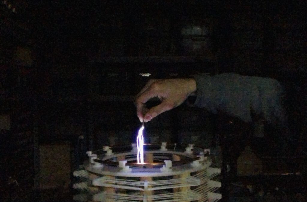
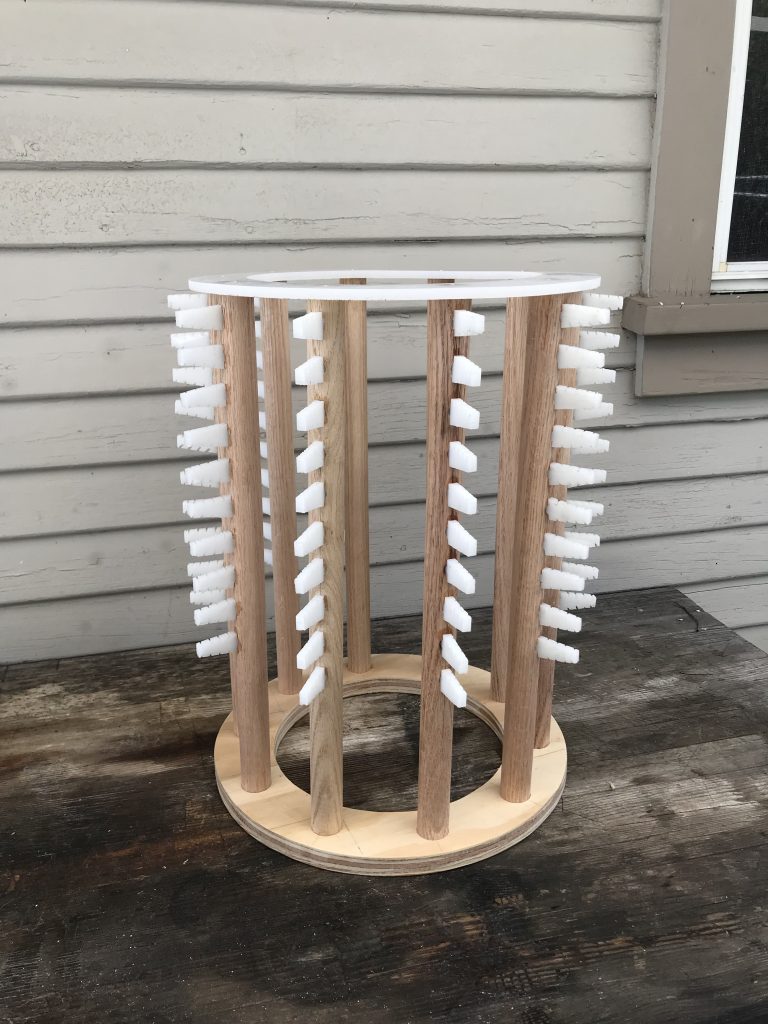
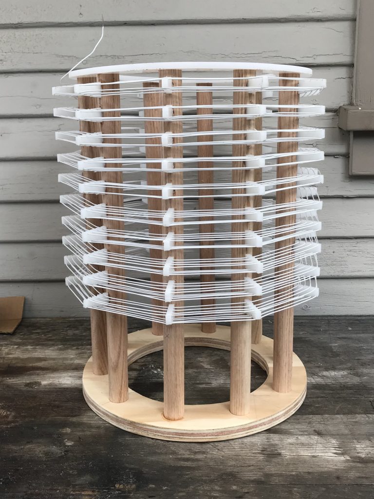
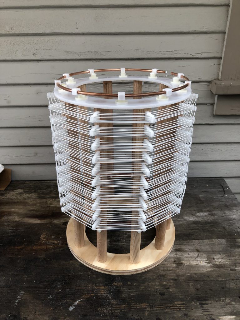
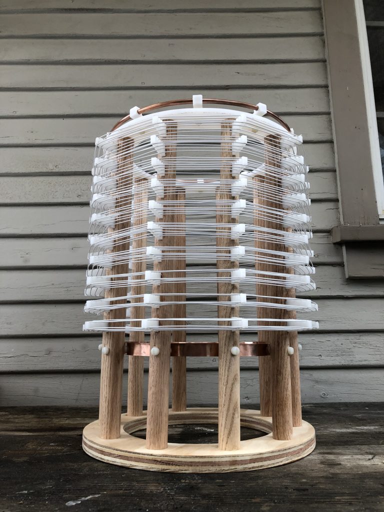
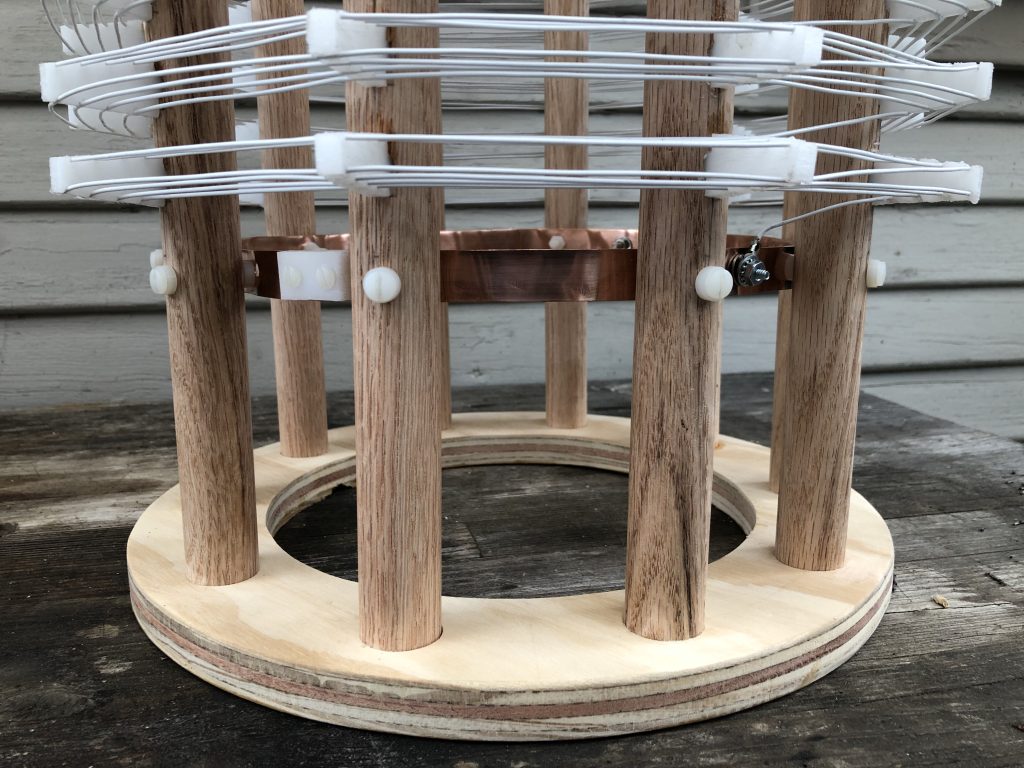
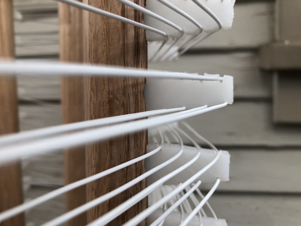
The following images depict the first attempt of replicating a potential-shunt coil, as employed in the original Alexanderson Antenna transmission design. Such antenna configurations were employed in Bolinas California, with one example (Grimeton SAQ) still in operational status. The potential coil replicated, shown in figure 1, consists of an eight foot wide by 6 foot tall coil, consisting of ten individual winding layers. Each layer possesses supporting insulators for holding eight conductors in total per layer. The novel simplicity of a multiplicity of coil windings upon a single form, allows for the achievement of low frequency (L.F.) operation, whilst maintaining efficiency to a decent degree, as well as a lessening self-capacity, in contrast to vertically wound L.F. coils.

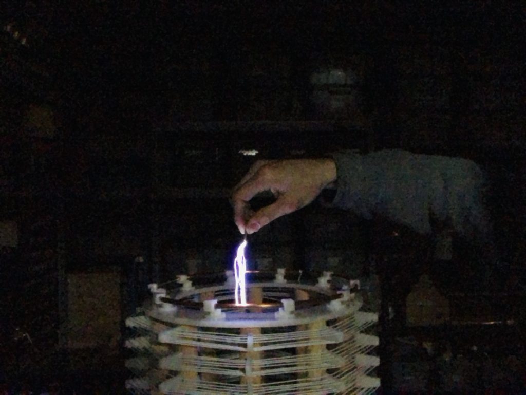
The scale replica of the potential coil, (figures 2-8), does not represent a scaled frequency of the original 130 kilocycles, but rather a final measured self-resonant frequency of 1080 kilocycles. It should be noted, that this frequency is irrespective to any external electrical loading, as initially determined via an RF signal generator and a series connected copper plate of low capacity. The determined proportional scale of the replicated coil is approximately 1:6. Hence, the coil’s diameter is 14.25 inches, and its height being 10.5 inches. Thereby, the total length of coiled conductor becomes 2,716 inches, or conversely, 226 feet. This approximates to a calculated quarter wavelength oscillation of 1087 kilocycles.
Share this:
- Click to share on Twitter (Opens in new window)
- Click to share on Facebook (Opens in new window)
- Click to share on Pinterest (Opens in new window)
- Click to share on LinkedIn (Opens in new window)
- More
- Click to share on Reddit (Opens in new window)
- Click to share on WhatsApp (Opens in new window)
- Click to share on Mastodon (Opens in new window)
- Click to share on Telegram (Opens in new window)
- Click to share on Tumblr (Opens in new window)
- Click to share on Nextdoor (Opens in new window)
- Click to share on Pocket (Opens in new window)
- Click to email a link to a friend (Opens in new window)
