h
Measuring Wave Velocity of Tesla Based Transmission
In regards to determine the effective velocity of longitudinal transmission, I have not seen any quantative researches. Hence, I have looked to my local AM radio station for a reference. This station (KAZN) is located exactly 4.4359 miles from my test point, and broadcasts on a frequency of 1300 kc. Therefore in any attempt to receive the tower’s overground signal, no ionospheric propagation reflection delay will exist. As it is merely the groundwave which presents itself at these short distances.
This experiment is comprised of two different receivers: a Tesla transformer crystal radio setup, and a 1920’s single coil crystal set. The Tesla receiver is Earthed directly to a grounded network, whereas the other set employs an antenna and ground as well. A Rigol 1054z oscilloscope is used to analyze the phase shift of the waveforms.
In any circumstance, whether it be any local station, or different time of reception, the longitudinal wave broadcasted by the AM transmitter always leads the waveform of the overground signal. That is, the overground signal or transverse electromagnetic wave lags some degree, given it propagates at nearly the speed of light. Taking into consideration the distance this signal must traverse, and the velocity of light in air (186,228 mi/sec.), it takes approximately 0.0000238197 seconds for it to arrive at the receiving antenna. Hence, we can use this as a reference point in determining the velocity of the telluric wave.
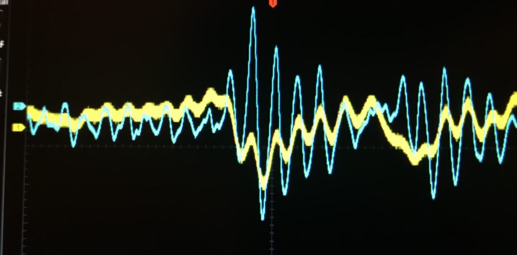
The following are measurements taken using the KAZN station. Note that it is the audio which is analyzed, so that any receiver phase shifting is not interpreted. The delay time is relating to the advancement of the longitudinal signal.
Horizontal Time Scale: 10uS
Delay Time
3.3us
100ns
100us
500ns
1.5us
900ns
100ns
2.3us
500ns
700ns
100ns
100ns
10.7us
1.5us
100ns
2.7us
2.3us
100ns
100ns
2.1us
100ns
3us
100ns
Average: 5.7782uS
Average Velocity: 245,872 mi/sec.
Horizontal Time Scale: 500nS
Delay Time
125ns
460ns
65ns
45ns
145ns
190ns
30ns
25ns
125ns
560ns
650ns
25ns
5ns
85ns
100ns
70ns
40ns
70ns
25ns
75ns
45ns
30ns
55ns
Average: 132.3912nS
Average Velocity: 187,269 mi/sec.
Hosrizontal Time Scale: 20uS
Delay Time:
1.8us
200ns
200ns
2us
1.8us
5.8us
1.0us
200ns
1.0us
1.8us
200ns
2.6us
22us
200ns
1.0us
12.60us
200ns
200ns
1.8us
400ns
1.4us
1.8us
2.6us
Average: 3.1217uS
Average Velocity: 214,315 mi/sec.
Horizontal Time Scale: 100uS
Delay Time
5us
1us
2us
2us
7us
3us
3us
6us
1us
219us
4us
22us
3us
1us
5us
3us
1us
1us
4us
3us
1us
1us
2us
Average: 4.42uS
Average Velocity: 228,772 mi/sec.
h
h
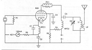
CW Tube Transmitter
A 6L6 CW transmitter has been constructed for Tesla related communication experiments. The total power output of the transmitter is roughly 10 watts.
h
h
h
AM Broadcast Transmitter
The following is a homebuilt AM tube transmitter, for use in Tesla related transmission, and for home use. It is of moderate power, and employs an external speaker to drive its audio.
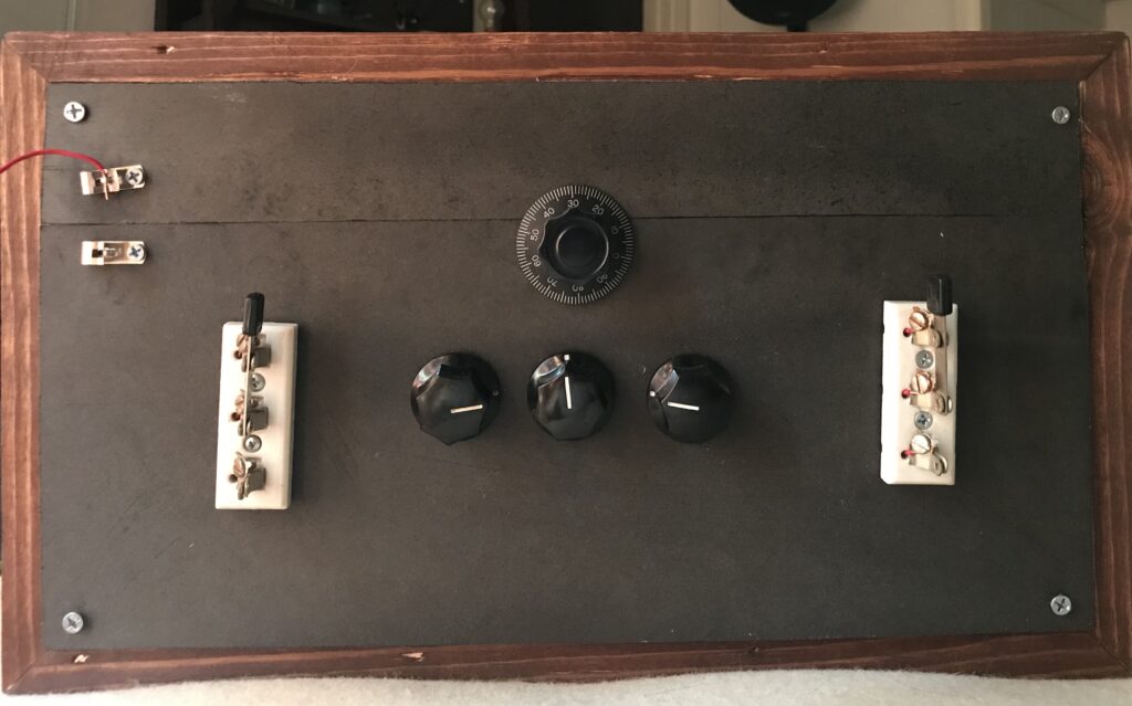
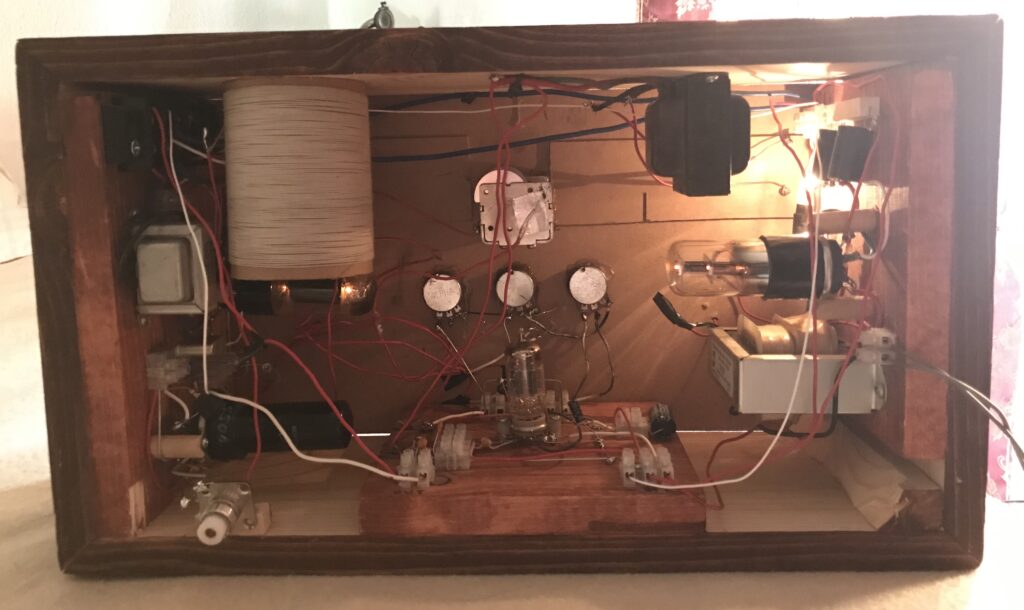
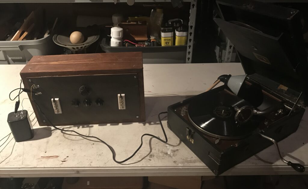
Further evolution of the set will involve various RF amplifier stages, as well as more advanced coil construction.
